
TM 5-3805-293-23-3
0131
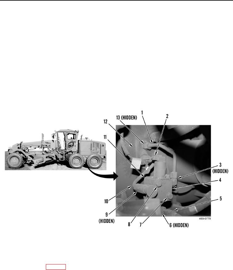
INSTALLATION CONTINUED
4. Install differential lock control valve (Figure 10, Item 4), two washers (Figure 10, Item 8) and bolts (Figure 10,
Item 7) on bracket (Figure 10, Item 11).
5. Connect harness connector (Figure 10, Item 2) to differential lock control valve (Figure 10, Item 4).
6. Install new O-ring (Figure 10, Item 6) and connect hose (Figure 10, Item 5) to differential lock control valve
(Figure 10, Item 4).
7. Install tube (Figure 10, Item 10) on machine.
8. Install two new O-rings (Figure 10, Item 9) and connect tube (Figure 10, Item10) to housing (Figure 10,
Item 12).
9. Connect tube (Figure 10, Item 10) to differential lock control valve (Figure 10, Item 4).
10. Install tube (Figure 10, Item 1) on machine.
11. Install new O-ring (Figure 10, Item 3) and connect tube (Figure 10, Item 1) to differential lock control valve
(Figure 10, Item 4).
12. Install new O-ring (Figure 10, Item 13) and connect tube (Figure 10, Item 1) to housing (Figure 10, Item 12).
Figure 10. Differential Lock Control Lines and Hose.
00131
END OF TASK
FOLLOW-ON TASKS
000131
Powertrain oil refilled (WP 0131).
END OF TASK
END OF WORK PACKAGE