TM 5-3805-293-23-3
0123
REMOVAL CONTINUED
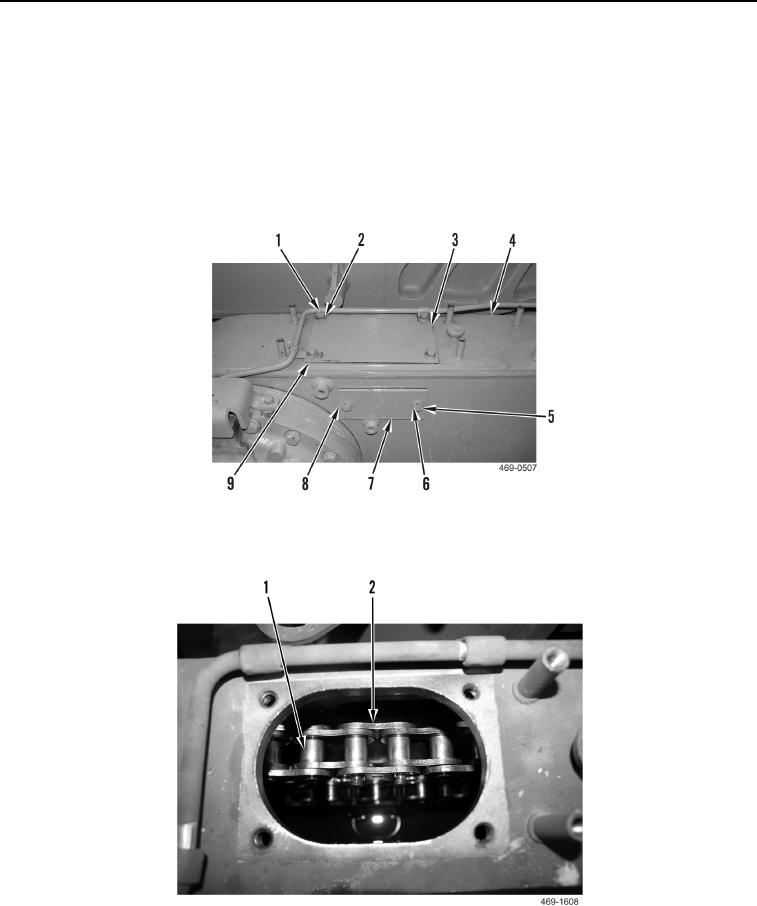
6. Remove four bolts (Figure 4, Item 1), washers (Figure 4, Item 2), cover (Figure 4, Item 3), and gasket
(Figure 4, Item 9) from tandem housing (Figure 4, Item 4). Position clamps aside. Discard gasket.
N OT E
Note the position of notch on cover for installation purposes.
7. Remove two bolts (Figure 4, Item 5), washers (Figure 4, Item 6), cover (Figure 4, Item 7), and gasket (Figure 4,
Item 8) from tandem housing (Figure 4, Item 4). Discard gasket.
Figure 4. Tandem Housing Access Covers.
0123
8. Turn wheel spindle assembly until master link (Figure 5, Item 2) on chain assembly (Figure 5, Item 1) appears.
Figure 5. Chain Assembly Master Link.
0123

