
TM 5-3805-293-23-3
0118
INSTALLATION CONTINUED
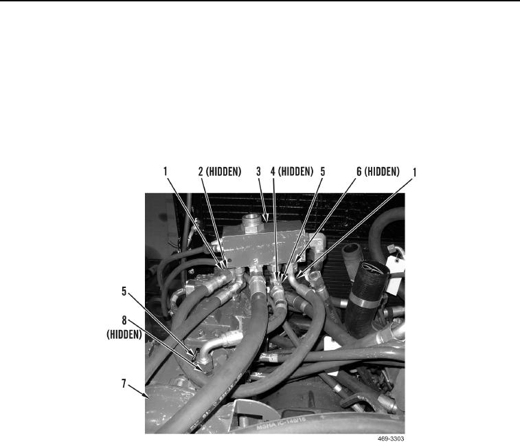
16. Install hydraulic hose (Figure 14, Item 1) on machine. Install new O-ring (Figure 14, Item 6) and connect
hydraulic hose to elbow on AWD control manifold (Figure 14, Item 3).
17. Install hydraulic hose (Figure 14, Item 5) on machine. Install new O-ring (Figure 14, Item 4) and connect
hydraulic hose to AWD control manifold (Figure 14, Item 3).
18. Install new O-ring (Figure 14, Item 8) and connect hydraulic hose (Figure 14, Item 5) to elbow on AWD piston
pump (Figure 14, Item 7).
19. Install new O-ring (Figure 14, Item 2) and connect hydraulic hose (Figure 14, Item 1) to AWD piston pump
(Figure 14, Item 7).
Figure 14. AWD Control Manifold and AWD Pumps.
0118
END OF TASK
FOLLOW-ON TASKS
000118
Install hydraulic system service pack (WP 0219).
END OF TASK
END OF WORK PACKAGE