
TM 5-3805-293-23-3
0118
INSTALLATION
000118
N OT E
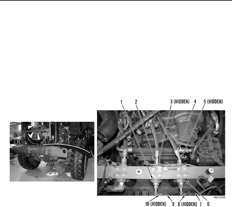
Install all lines as marked and tagged during removal.
1. Install hydraulic hose (Figure 8, Item 7) on machine. Install new O-ring (Figure 8, Item 8) and connect hydraulic
hose to elbow on right charge filter (Figure 8, Item 6).
2. Install hydraulic hose (Figure 8, Item 9) on machine. Install new O-ring (Figure 8, Item 10) and connect
hydraulic hose to elbow on left charge filter (Figure 8, Item 1).
3. Install hydraulic hose (Figure 8, Item 4) on machine. Install new O-ring (Figure 8, Item 5) and connect hydraulic
hose to right charge filter (Figure 8, Item 6).
4. Install hydraulic hose (Figure 8, Item 2) on machine. Install new O-ring (Figure 8, Item 3) and connect hydraulic
hose to left charge filter (Figure 8, Item 1).
Figure 8. Charge Filter Lines.
0118