
TM 5-3805-293-23-3
0118
INSTALLATION CONTINUED
000118
N OT E
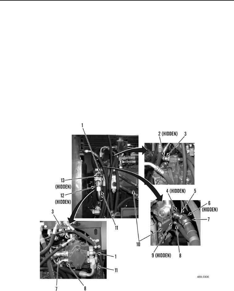
Rear view of all wheel drive pump with cooling module removed is shown in Figure 11 for
clarity.
7. Install new O-ring (Figure 11, Item 9) and connect hydraulic hose (Figure 11, Item 8) to AWD pump (Figure 11,
Item 10).
8. Install new O-ring (Figure 11, Item 4) and elbow (Figure 11, Item 5) on AWD pump (Figure 11, Item 10).
9. Install hydraulic hose (Figure 11, Item 7) on machine. Install new O-ring (Figure 11, Item 6) and connect
hydraulic hose to elbow (Figure 11, Item 5).
10. Install new O-ring (Figure 11, Item 2) and connect hydraulic hose (Figure 11, Item 3) to elbow on AWD pump
(Figure 11, Item 10).
11. Install hydraulic hose (Figure 11, Item 11) on machine. Install new O-ring (Figure 11, Item 12) and connect
hydraulic hose to elbow on AWD pump (Figure 11, Item 10).
12. Install new O-ring (Figure 11, Item 13) and connect hydraulic hose (Figure 11, Item 1) to elbow on AWD pump
(Figure 11, Item 10).
Figure 11. AWD Pump Lines.
0118