
TM 5-3805-293-23-3
0044
RELIEF VALVE (SECONDARY STEERING) TEST CONTINUED
00044
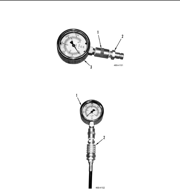
3. Assemble pressure gauge assembly. Install pipe coupling (Figure 129, Item 1) and hose coupling (Figure 129,
Item 2) on both 5,000 psi pressure gauges (Figure 129, Item 3).
Figure 129. Pressure Gauge Assembly.
0044
4. Connect hose (Figure 130, Item 2) to pressure gauge assembly (Figure 130, Item 1).
Figure 130. Pressure Gauge Assembly and Hose.
0044