
TM 5-3805-293-23-3
0044
TEST FOR THE SIGNAL RESOLVER CONTINUED
00044
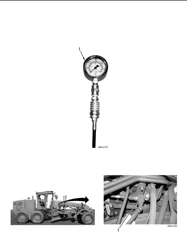
7. Move wheel lean cylinder to end of stroke and stall cylinder (TM 5-3805-293-10). The pressure gauge
(Figure 122, Item 1) should read 3,481 73 psi (24,000 500 kPa), indicating signal resolver has shifted cor-
rectly. Release wheel lean cylinder control.
8. Move steering cylinder right to left and left to right several times (TM 5-3805-293-10). The pressure gauge
(Figure 122, Item 1) should read 1,827 psi (12,600 kPa), indicating signal resolver (Figure 122, Item 1) has
shifted correctly.
Figure 122. Pressure Gauge.
0044
9. If pressure readings do not change, replace signal resolver (Figure 123, Item 1) (WP 0246).
Figure 123. Signal Resolver.
0044