
TM 5-3805-293-23-3
0044
RELIEF VALVE (SECONDARY STEERING) TEST CONTINUED
00044
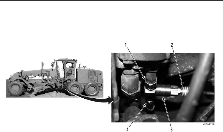
10. Connect hydraulic line (Figure 133, Item 4) to tee body assembly (Figure 133, Item 3), and connect tee body
assembly (Figure 133, Item 3) to secondary steering pump fitting (Figure 133, Item 1).
11. Connect hose and gauge assembly (Figure 133, Item 2) to tee body assembly (Figure 133, Item 3).
Figure 133. Secondary Steering Pump.
0044
12. Start engine (TM 5-3805-293-10).
13. Press implement lockout switch to ON position (TM 5-3805-293-10).
14. Depress secondary steering test switch while monitoring pressure gauge (TM 5-3805-293-10). The pressure
should be 2,500 psi (17,225 kPa).
a. If pressure is not achieved, replace relief valve (WP 0175).
b. If pressure is achieved, proceed to step 15.
15. Stop engine (TM 5-3805-293-10).
16. Remove and disassemble hose and gauge assembly.