TM 5-3805-293-23-3
0044
AXLE TOE-IN (FRONT) ADJUST
00044
1. Park machine on hard, level surface (TM 5-3805-293-10).
2. Install wheel lean locking bolt into lean bar (TM 5-3805-293-10).
3. Use blade to raise front of machine until front wheels are off the ground (TM 5-3805-293-10).
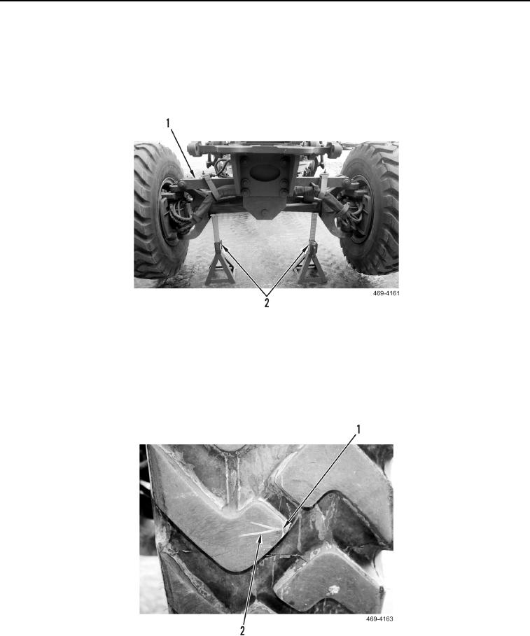
4. Place vehicle support stands (Figure 136, Item 2) at both ends of front axle (Figure 136, Item 1).
Figure 136. Vehicle Support Stands.
0044
5. Make sure front wheels are in straight-ahead position (TM 5-3805-293-10).
6. Mark both front tires at centerline of tread while rotating wheels.
7. Mark a V (Figure 137, Item 2) on front of each front tire at centerline of front axle (as measured from ground)
near center of tread (Figure 137, Item 1).
Figure 137. Mark Tires.
0044

