
TM 5-3805-293-23-3
0044
SERVICE BRAKE SYSTEM PRESSURE TEST CONTINUED
N OT E
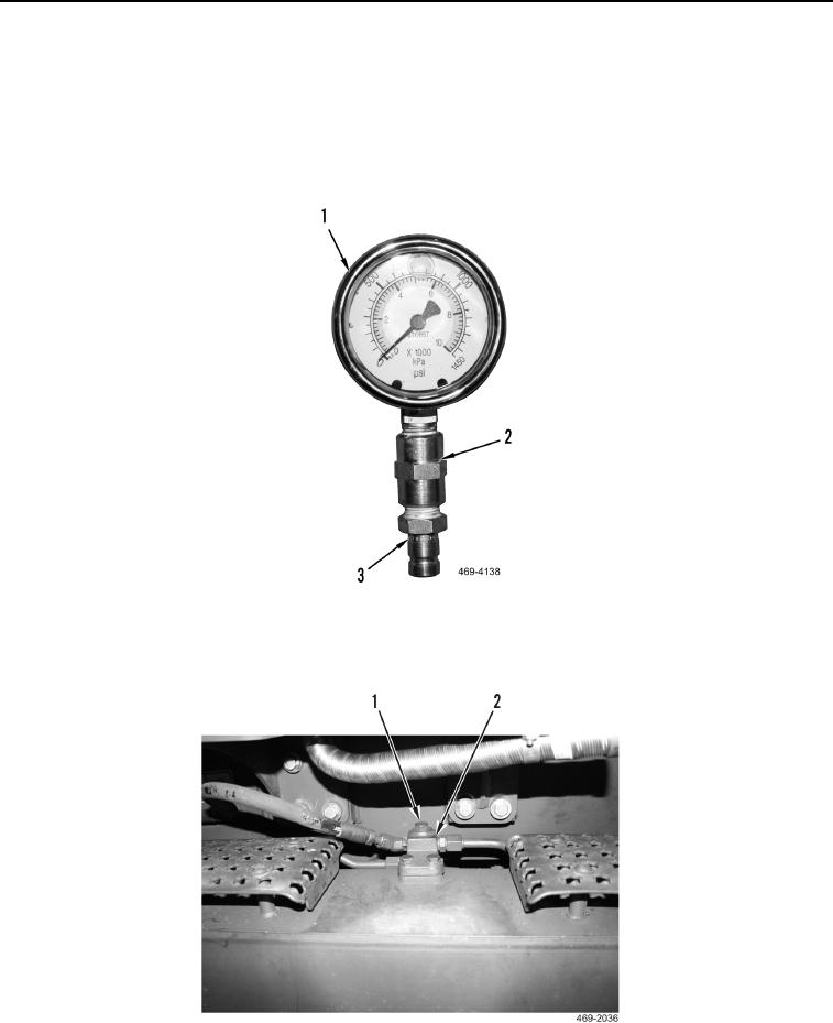
Apply sealing compound on pipe coupling and pressure gauge threads.
4. Assemble two 1,450 psi pressure gauges. Install pipe coupling (Figure 71, Item 2) and hose coupling (Figure
71, Item 3) on both pressure gauges (Figure 71, Item 1).
Figure 71. 1,450 PSI Pressure Gauge.
0044
5. Remove plug (Figure 72, Item 1) from left service brake test port (Figure 72, Item 2).
Figure 72. Left Service Brake Test Port.
0044