
TM 5-3805-293-23-3
0044
BRAKE SYSTEM AIR PURGE CONTINUED
N OT E
Ensure correct oil level in hydraulic oil tank is maintained throughout air removal
procedure.
3. Check hydraulic tank oil level (TM 5-3805-293-10).
4. Start engine and synchronize left steering joystick (TM 5-3805-293-10).
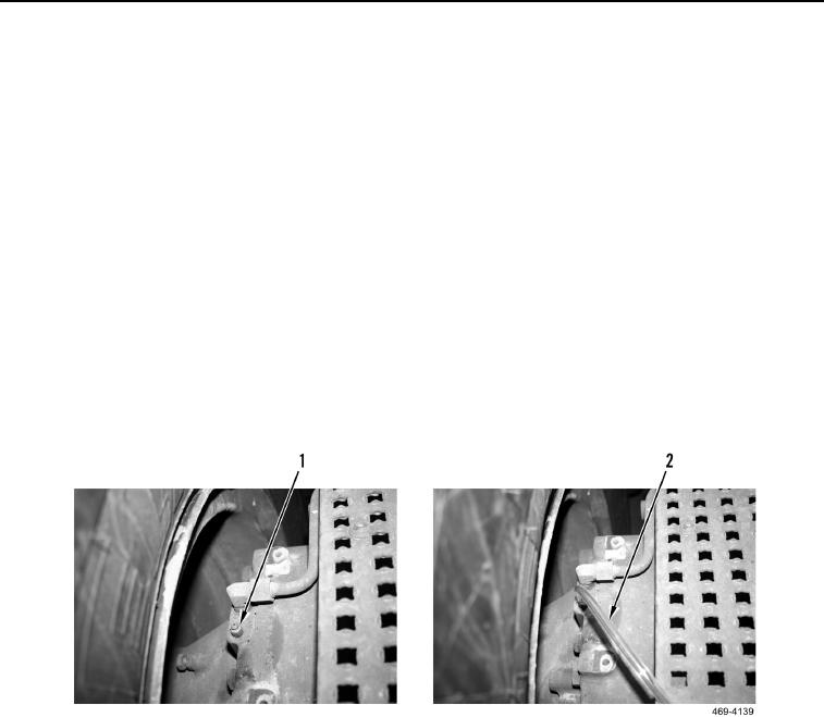
5. Fasten one end of a transparent tube (Figure 67, Item 2) to air purge screw (Figure 67, Item 1) and other end
of tube into container for collecting hydraulic oil.
WARN I N G
Personal injury or death can result if two persons are not used in the following procedure.
6. With assistance, maintain constant pressure on brake pedal, and open air purge screw (Figure 67, Item 1).
7. As hydraulic oil flows through tube (Figure 67, Item 2), allow oil to flow into container until no air bubbles are
visible.
8. Tighten air purge screw (Figure 67, Item 1), remove hose (Figure 67, Item 2) and release brake pedal.
Figure 67. Air Purge Screw and Drain Hose.
0044