
TM 5-3805-293-23-2
0034
CAN DATA LINK CIRCUIT TEST CONTINUED
Test Step 1. Test CAN Data Circuit
00034
C AU T I O N
Do not use excessive force when pulling on wires. Damage to wires or connectors may
result.
N OT E
Always inspect the harness connectors that ae involved in the circuit. Poor connections
r
can often be the cause of the problem in an electrical circuit. Verify that all connections in
the circuit are clean and secure, and that all connections are in good condition. Gently pull
on each wire, if a problem with a connection is found, correct the problem and verify that
this diagnostic code is active before performing this procedure.
Perform open or short circuit test at each harn ss connection to identify correct harness to
e
replace.
Perform this test only if condition is active.
1. Turn the ignition switch and battery disconnect switch to the OFF position (TM 5-3805-293-10).
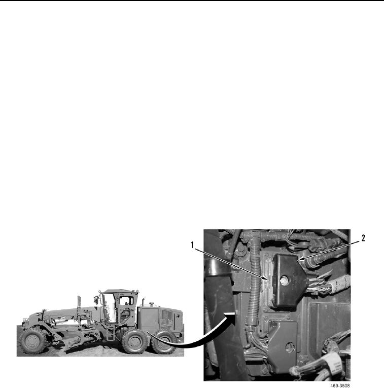
2. Disconnect the engine ECM harness connector FA-C17 (Figure 1, Item 2) from engine ECM J1 (Figure 1,
Item 1) (WP 0067).
Figure 1. Engine ECM Harness Connector FA-C17.
0034