POWER TRAIN
DISASSEMBLY AND ASSEMBLY
TM 5-3805-263-14&P-2
TRANSMISSION GEARS
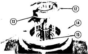
10. Install clutch piston (14) on the shaft.
NOTE: The piston goes over the seal rings on the
shaft. The seal rings must be in a center position on
the shaft to make it possible for the drum for the
clutch to be installed.
11. Make sure the groove (slot) in the piston is
in alignment with dowel (15) in the shaft.
12. Install seal ring (13) on plate (12). Install
the O-ring seal under the plate.
13. lnstall the plate on the shaft. Make sure the
groove (slot) in the plate is in alignment
with the dowel in the shaft.
14. Install the bearing and the spacer on the
shaft.
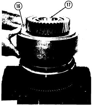
15. Install the lock ring, the spacer and two
bearing cups (17) in the gear for hub (16).
16. Install hub (16) and the gear on the shaft
and over the clutch plates and discs.
NOTE: The seal rings on the shaft must be in a
center position to make it possible for the drum to
be installed.
17.
18.
19.
20.
Install the other bearing in the gear for the
hub.
Heat bearing (19) to a temperature of
275° F (135° C) in oil. Install the bearing
on the shaft.
Install two 3/8”-16 NC forged eyebolts (20)
in the bottom of the input gear. Put a bar
through the eyebolts. Put 4S9416 Anti-
Seize Compound on the threads and the
face of nut (18). Install the lock and nut
(18) on the shaft.
Tighten nut (18) with tool (A) to a torque
of 80 ± 5 lb. ft. (11.1 ± 0.7 mkg). Bend the
tab of the lock into the groove (slot) in the
nut. Remove tool (A), the bar and the two
eyebolts.
2-113