VEHICLE SYSTEMS
TM 5-3805-263-14&P-3
COMBINATION VALVE
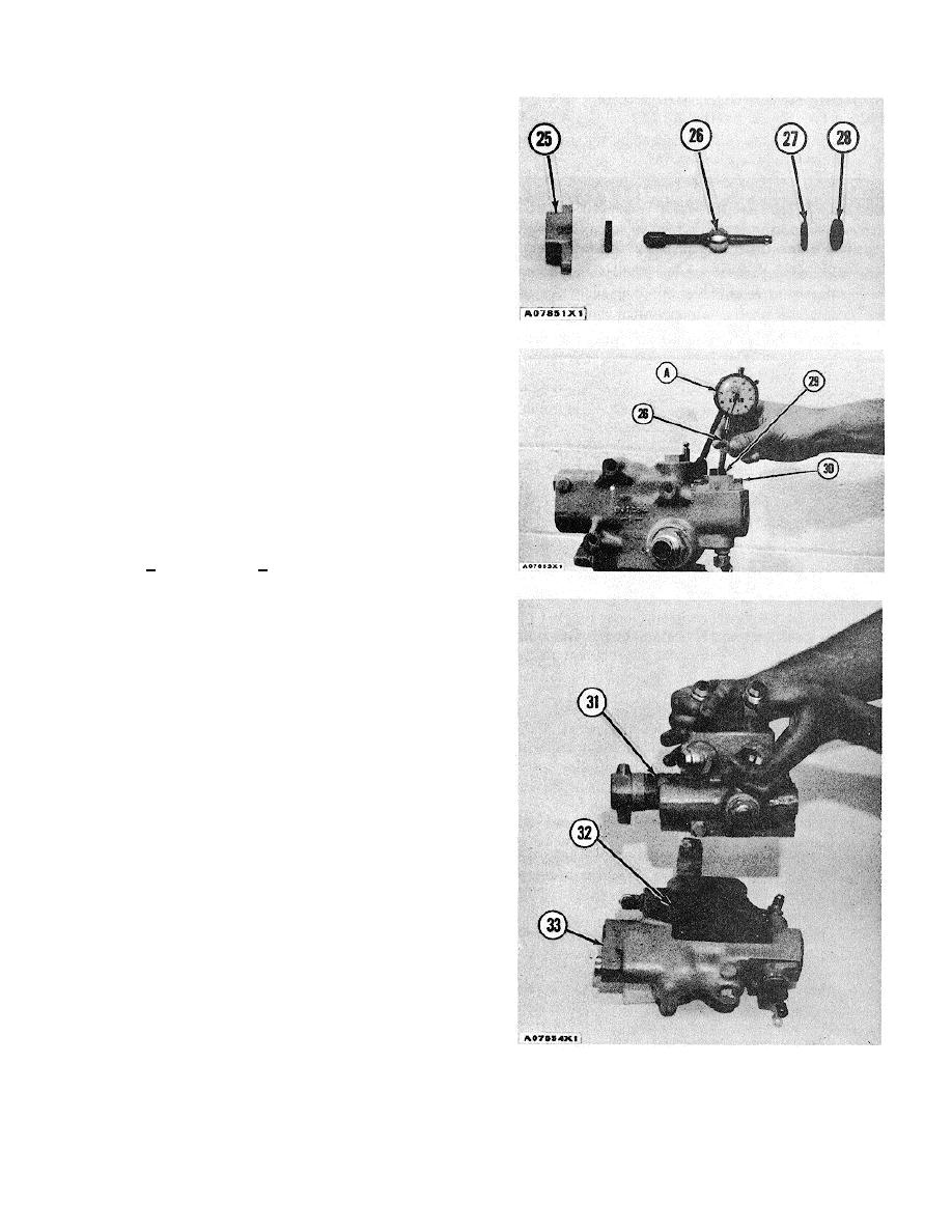
9. Put ring and seal (27) and bearings (28) in
position on lever (26). Put the lever in position in
housing (25). Install the O-ring in the bottom of
housing (25).
10. Put the unloading valve in position in a vise.
11. Install the lever assembly in the valve. Install the
lockwashers and bolts (30) that hold it. Install
screw (29) in the housing.
12. Put tooling (A) in position as shown. Lift lever
(26) with a force of 25 lb. (110 N). Turn screw
(29) in or out until the end play of the lever is
.006 + .003 in. (0.15 + 0.08 mm).
13. Remove tooling (A). Install the nut on screw
(29). Install the boot on the nut.
14. Install 0-ring seals (32) in the unloading valve.
15. Putrelief valve (31) in position on unloading valve
(33). Install the bolts that hold the relief valve to
the unloading valve end by:
a) install combination valve
3-257


