DISASSEMBLY AND ASSEMBLY
TM 5-3805-263-14&P-3
CONTROL VALVES
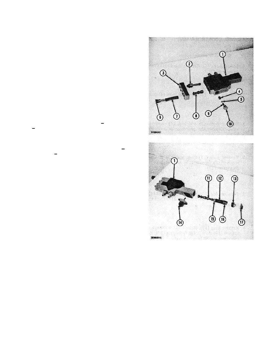
ASSEMBLE CONTROL VALVES
1. Inspect the O-ring seals.
Replace the O-ring
seals if necessary
2. Put sleeve (2) in position in body (1). Put spool
(8) in position in body (1).
3. Put cover (3) in position on body (1). Install the
bolts that hold the cover to the body.
4. Install spring (7) and plug (6)'with the necessary
shims and spacers. See VALVE FOR FLOW
CONTROL in TESTING AND ADJUSTING.
Tighten plug (6) to a torque of 35 + 5 lb. ft. (45
+ 7 N.m).
5. Clean the screen in seat (4). Install seat (4) in
body (1). Tighten seat (4) to a torque of 12 + 2
lb. ft. (17 + 3 N.m). Put ball (5) in position in
seat (4). Install spring (9) and plug (10).
6. Install retainer (15) on stem (11). Put spring (12)
in position on retainer (15) over the stem. Install
retainer (16) that holds spring (12). Make sure
the opening in retainer (16) is in alignment with
the hole in stem (11). Put stem (11) in position in
body (1).
7. Put lever (14) in position in the body. Make sure
the end of the lever is in the hole in the stem.
Install the bolts that hold the lever to the body.
8. Install plug (13) in 'the body. Tighten plug (13) to
get minimum end clearance of the stem. Put
lock (17) in position over plug (13). Install the
bolts that hold the lock to the body.
3-252


