DISASSEMBLY AND ASSEMBLY
TM 5-3805-263-14&P-3
BRAKE CONTROL VALVE
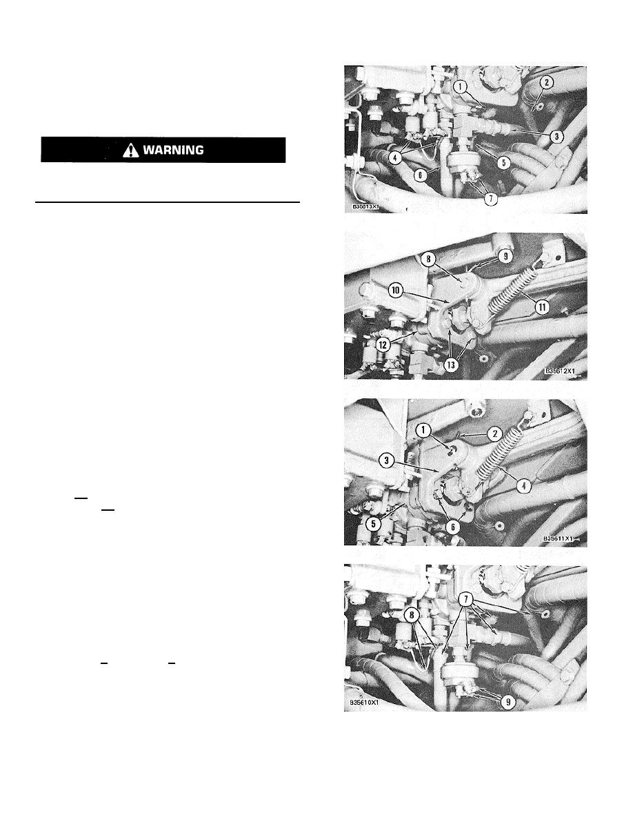
REMOVE BRAKE CONTROL VALVE.
1. Release the air pressure in the air tank. Loosen
the bleed valves as necessary.
Do not disconnect any air lines from
the brake control valve until the air
pressure is zero.
2. Put identification on all air lines and electric wires
as to their location on the brake control valve
and switches.
3. Disconnect five air lines (1), (2), (3), (5) and (6).
Disconnect wires (4) and (7) from the pressure
indicator switch and the stop light switch,
respectively.
4. Disconnect spring (11) from pedal. Remove
cotter pin (9) from pin (8) and bracket (10).
5. Remove pin (8) from bracket and pedal.
Remove three bolts (13)> 6. Remove brake
control valve (12).
INSTALL BRAKE CONTROL VALVE
1. Put brake control valve (5) in position on the
machine. Install the bolts (6) that hold bracket.
(3) and the brake control valve to the machine.
2. Put pedal in position on bracket and install pin
(1) to hold pedal to bracket. Install cotter pin (2)
in pin (1).
3. Connect spring (4) from floor plate to pedal.
4. Connect air lines (7) to their correct location on
the brake control valve.
5. Connect wires (9) to their correct location on the
stop light switch. Connect two wires (8) to their
correct location on the pressure indicator switch.
6. Make an adjustment to the screw in the frame
under the pedal to get valve stem movement
of.34 + .03 in. (8.6 + 0.8 mm) with the pedal in
the "DOWN" position .
3-258


