TM 5-3805-263-14&P-3
SUPPLEMENTAL STEERING SYSTEM
2. Loss of hydraulic oil pressure with the dump valve
switch and the governor switch in their normal
operating positions.
The machine's batteries must have a normal charge and
the supplemental steering electrical system must be
3. The hydraulic pressure switch open.
okay. A low charge condition, or any defect in the battery,
battery cells, or electrical circuit can cause loss of
With these conditions present, electronic module (1)
supplemental steering and could result in personal injury
closes magnetic switch relay (9). This completes the
and/or damage to the machine.
circuit to supplemental steering pump motor (8) and to
motor status light (5). At the same time, electronic
control module (I) actuates the electronic monitoring
system (EMS)
panel indicator LED (6), master fault
light (7), and horn.
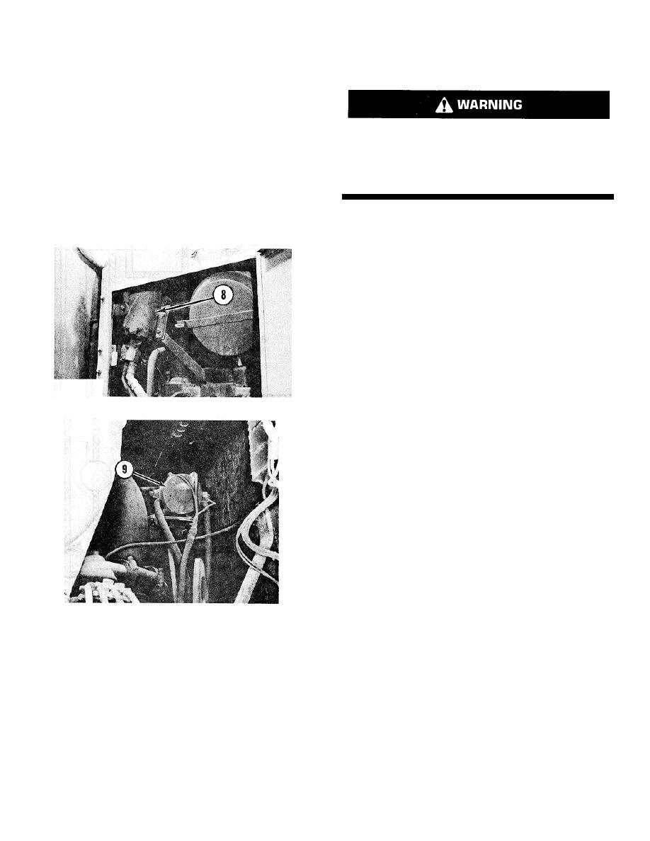
SUPPLEMENTAL STEERING MOTOR
8. Motor.
MAGNETIC SWITCH RELAY
9. Magnetic switch relay.
The supplemental steering pump motor (8) can also
be actuated by holding the spring loaded auto-matic
manual switch (4) in the manual position. This action will
by-pass electronic control module (1) and its four sensor
inputs and turn ON motor status light (5). This position of
the AUTO/ MANUAL switch is generally used only to test
the supplemental steering pump and the motor status
light, or turn the front wheels while testing the system.
3-37


