TM 5-3805-263-14&P-3
SYSTEMS OPERATION
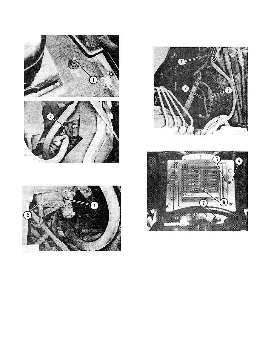
ELECTRONIC CONTROL MODULE
(SUPPLEMENTAL STEERING)
ELECTRONIC CONTROL MODULE
1. Electronic control module. 2. 2-pin sure seal connector.
3. 9-pin sure seal connector.
DUMP VALVE SWITCH
1. Dump valve control lever. 2. Switch.
STEERING PRESSURE SWITCH
AUTO/MANUAL SWITCH AND WARNING SYSTEM
1. Auto/Manual switch. 5. Motor status light. 6. Panel
indicator LED. 7. Master fault light.
The electronic control module (1) controls the three
STEERING PRESSURE SWITCH
second power-up test and [depending on switch (4)
1. Combination valve (partial view). 2. Pressure switch.
position] controls automatic actuation of
the
supplemental steering system.
The steering pressure switch (2) is mounted on the relief
valve group body of combination valve (1). When the
In the automatic switch position, the following
governor and dump valve are in their normal operating
condition(s) must exist before electronic control module
positions and primary steering system pressure is lost
(1) actuates the supplemental steering motor and
(either as a result of engine failure or hydraulic system
status light:
failure upstream of the steering valve), the steering
pressure switch (2) opens. This provides the input to the
1. The electronic control module (I) must have been
electronic control module to turn the supplemental
actuated (placed in ready position) by voltage from
steering ON.
the alternator "R" terminal.
3-36


