TM 5-3805-263-14&P-3
SUPPLEMENTAL STEERING SYSTEM
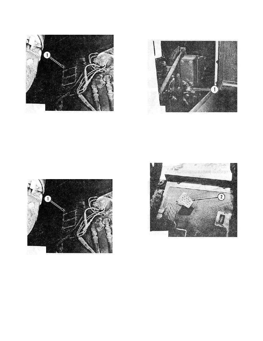
ENGINE GOVERNOR SWITCH
ELECTRONIC CONTROL MODULE
ENGINE GOVERNOR SWITCH
(SUPPLEMENTAL STEERING)
1. Switch.
1. Electronic control module.
The engine governor switch (I) is normally open
The electronic control module (I) (supplemental
(N.O.). In the closed position, the switch prevents
steering) turns on the supplemental steering motor,
automatic actuation of the supplemental steering motor
motor status light, Electronic Monitoring System (EMS)
during normal engine shutdown.
indicator light, master fault light and horn through four
inputs. These four inputs are from the alternator "R"
Pull up by hand accelerator pedal (2) to both
terminal, the engine governor switch, the unloading
shutdown the engine and close governor switch (1).
(dump) valve switch, and the steering hydraulic pressure
switch.
ALTERNATOR "R" TERMINAL
ACCELERATOR PEDAL
2. Accelerator pedal.
DUMP VALVE SWITCH
ALTERNATOR (NOT INSTALLED)
1. "R" terminal.
The dump (unloading) valve (1) is used to cycle oil
The electronic control is connected to alternator "R"
back to the hydraulic tank. This removes the parasitic
terminal ( ). After engine start-up voltage from alternator
load of the implement hydraulic pump from the starter
"R" terminal (I) activates an internal latch (electronic
during cold weather starting of the engine. The dump
"fastener") in the electronic control module to activate the
valve switch (2) prevents automatic actuation of the
automatic supplemental steering system. After start-up,
supplemental steering motor due to hydraulic power loss
the latch makes the supplemental steering system
while dump valve control lever (1) is depressed.
independent of the alternator "R" terminal current. It is
unlatched by the governor switch or the disconnect
switch.
3-35


