TM 53805-261-34
EARTHMOVING EQUIPMENT COMPONENTS MAINTENANCE. (cont.)
12-3. Blade Lift Bar Assembly. (Sheet 5 of E
INSTALLATION (cont.)
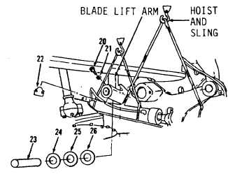
3.
Install two washers (26, 25 and
24) between blade lift bar (34,
Figure 12-8) and blade lift arms.
Use two washers (26, 25 and 24)
as required to obtain 0.06 to
0.12 inch clearance between blade
lift bar (34) and lock plate.
4.
Install pin (23). Groove in pin
(23) must align with opening in
blade lift arm.
5.
Install lock (22), two washers
(21) and bolts (20).
6.
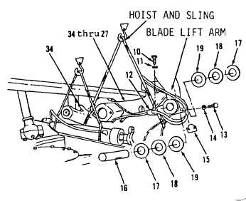
Install washers (19, 18 and 17)
between items 34 thru 27 as an
assembly (Figure 12-7) and blade
lift arms. Use washers (19, 18
and 17) as required to obtain
0.06 to 0.12 inch clearance
between blade lift bar (34) and
lock plate.
7.
Install pin (16). Groove in pin
(16) must align with opening in
blade lift arm.
8.
Install lock (15), two washers
(14) and bolts (13).
9.
Remove hoist and sling from items
34 thru 27 as an assembly.
10. Install clip (12), lockwasher
(11) and bolt (10) in blade lift
bar (34).
Figure 12-7.
Figure 12-8.
Go to Sheet 6
12-12