TM 5-3805-261-34
HYDRAULIC SYSTEM MAINTEANCE. (cont)
10-19.
Hydraulic Side Shift Cylinder. (Sheet 2 of 7)
REMOVAL
NOTE
Blade must be tilted all the
way forward.
1.
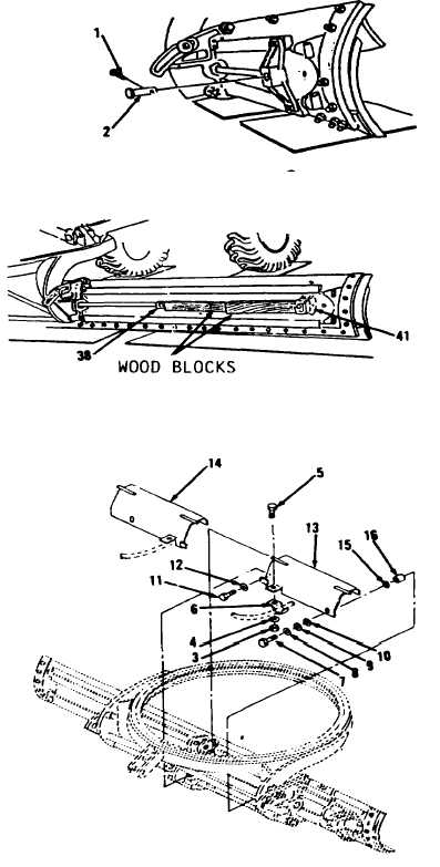
Remove cotter pin (1) and pin (2,
Figure 10-139). Discard cotter
pin (1).
2.
Start engine. Refer to TM 5-
3805-261-10.
3.
Retract rod end of cylinder (38,
Figure 10-140).
4.
Position wood blocks between rod
end of cylinder (38) and bracket
(41).
5.
Expand rod end of cylinder (38)
in operator’s compartment. Move
blade far enough to right to get
access to cylinder (38).
6.
Stop engine.
7.
Reduce hydraulic pressure to
zero. Refer to TM 5-3805-261-10.
8.
Remove wood blocks.
9.
Remove two nuts (3), washers (4),
bolts (5) and clamps (6, Figure
10-141).
10. Remove two bolts (7), washers (8
and 9) and spacers (10).
11. Remove two bolts (11) and washers
(12).
12. Remove guards (13 and 14), two
washers (15) and spacers (16).
Go to Sheet 3
10-110
Figure 10-139.
Figure 10-140.
Figure 10-141.

