TM 5-3805-261-34
HYDRAULIC SYSTEM MAINTENANCE. (cont)
10-10.
Hydraulic Control Valves. (Sheet 10 of 11)
ASSEMBLY (cont)
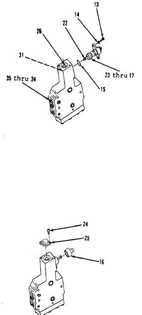
26.
Install new preformed packing
(15, Figure 10-99).
27.
Position items 23 thru 17 as an
assembly on items 35 thru 24 as
an assembly. Insert end of lever
(22) in hole at end of stem (31).
28.
Install two washers (14) and
bolts (13).
ADJUSTMENT
1.
Adjust plug (26). Tighten plug
(26) to remove end clearance from
stem (31). By movement of lever
(22) in the neutral position, end
clearance in the stem can be
felt. Do not over tighten plug
(26).
2.
Adjust screw (18, Figure 10-85).
Turn screw finder tight until it
is against one bearing (19), then
turn counterclockwise 45 degrees
to obtain lever (22) end
clearance of 0.006 inch.
3.
Hold nut (17) and tighten to 25
ft-lb torque.
ASSEMBLY
1.
Install lock (25) and two bolts
(24, Figure 10-100).
2.
Install boot (16).
Go to Sheet 11
Figure 10-99.
Figure 10-100.
10-66