TM 5-3805-261-34
HYDRAULIC SYSTEM MAINTENANCE.
10-10.
Hydraulic Control Valves. (Sheet 9 of 11)
ASSEMBLY
20.
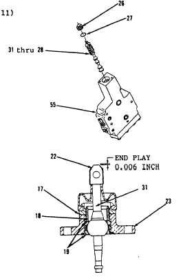
Install items 31 thru 28 as an
assembly in body (55, Figure
10-94), alining hole in end of
stem (31) with hole for lever
(22, Figure 10-95).
21.
Install new preformed packing
(27) and plug (26, Figure 10-94)
loosely.
22.
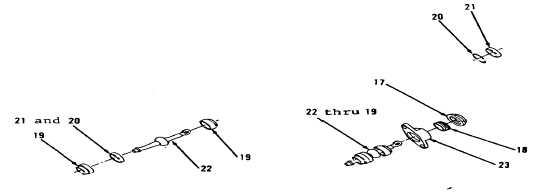
Install new preformed packing
(20) on ring (21, Figure 10-96).
23.
Position items 21 and 20 as an
assembly and two bearings (19) on
lever (22, Figure 10-97).
24.
Position items 22 thru 19 as an
assembly in housing (23, Figure
10-98),
25.
Install screw (18) and nut (17)
loosely.
Go to Sheet 10
Figure 10-94.
Figure 10-95.
Figure 10-96.
Figure 10-97.
Figure 10-98.
10-65


