TM 5-3805-261-34
STEERING MAINTENANCE.
8-5.
Steering Cylinder. (Sheet 4 of 6)
INSTALLATION
1.
Install nut (19) and socket (18) on cylinder (20,
Figure 8-15). Screw socket (18) and nut (19)
into cylinder (20) with the same amount of threads
exposed as recorded in removal.
2.
Tighten nut (19) while holding hex (21) end of rod.
3.
Install ring (17), spacer (16), bearing (15) and
spacer (14) in items 20 thru 18 as an assembly
(Figure 8-14).
4.
Install items 20 thru 18 as an assembly in axle
bracket and wheel spindle housing.
5.
Install washer (13), nut (12) and new cotter pin (11).
Tighten nut (12) to 103 ft-lb torque.
6.
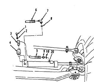
Install new preformed packing (10) and connector
(9) to cylinder (20, Figure 8-13).
7.
Install new preformed packing (8) and elbow (7).
8.
Connect hose assemblies (6 and 5).
9.
Install pin (4), clip (3), washer (2) and bolt (1).
10.
Remove leaning wheel lock pin. Refer to
TM 5-3805-261-10.
Go to Sheet 5
8-15
Figure 8-13.