TM 5-3805-261-34
TRANSMISSION MAINTENANCE. (cont)
5-9.
Control Relief Valve. (Sheet 2 of 6)
TESTING
NOTE
The following test is for
transmission pump relief
pressure.
Test must be made with
transmission hydraulic
system at normal operating
temperature.
All hose and tube
assemblies must be tagged
before disconnecting to aid
in Installation. Cap all
hose and tube ends to
prevent contamination.
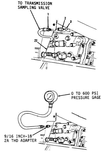
1.
Disconnect hose assembly (1) from
valve assembly (22, Figure 5-38)
from rear, left side of
transmission.
2.
Remove elbow (2) and preformed
packing (3). Discard preformed
packing (3).
3.
Using a 9/16 inch-18 2A TED
adapter, install 0 to 600 psi
pressure gage (Figure 5-39).
4.
Start engine. Refer to TM 5-
3805-261-10.
5.
Position transmission selection
lever in neutral. Read pressure
gage. Pump pressure must be 330
to 350 psi. Record pressure if
gage does not read within
specified range and contact
general support.
6.
Stop engine.
7.
Remove O to 600 psi pressure gage
and 9/16 inch-18 2A TED adapter.
Go to Sheet 3
5-36
Figure 5-38.
Figure 5-39.


