TM 5-3805-261-34
TRANSMISSION MAINTENANCE.
5-9.
Control Relief Valve. (Sheet 3 of 6)
TESTING
8.
Install new preformed packing (3)
and elbow (2, Figure 5-38).
9.
Connect hose assembly (1).
NOTE
The following test is for
transmission oil cooler
relief pressure.
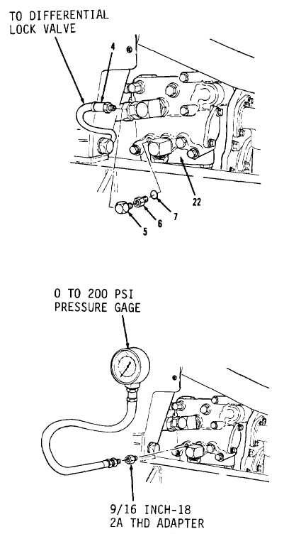
10. Disconnect hose assembly (4) from
valve assembly (22, Figure 5-40).
11. Remove elbow (5), adapter (6) and
preformed packing (7). Discard
preformed packing (7).
12. Using a 9/16 inch-18 2A THD
adapter, install 0 to 200 psi
pressure gage (Figure 5-41).
13. Start engine.
14. Position transmission selection
lever in first speed forward.
Read pressure gage. Pressure
gage must read 75 psi. Record
pressure if gage does not read
specified pressure and contact
direct support.
15. Stop engine.
16. Remove O to 200 psi pressure gage
and 9/16 inch-18 2A THD adapter.
17. Install new preformed packing
(7), adapter (6) and elbow (5,
Figure 5-40).
18. Connect hose assembly (4).
Go to Sheet 4
5-37
Figure 5-40.
Figure 5-41.

