TM 5-3805-261-34
TRANSMISSION MAINTENANCE. (cont)
5-9.
Control Relief Valve. (Sheet 6 of 6)
INSTALLATION
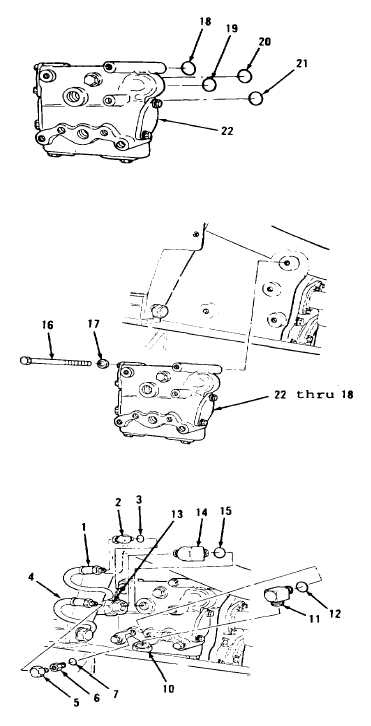
1.
Install new preformed packings
(21 thru 18) in valve assembly
(22, Figure 5-45).
2.
Position items 22 thru 18 as an
assembly (Figure 5-44) at rear,
left side of transmission.
3.
Install four washers (17) and
bolts (16).
4.
Install new preformed packing
(15) and elbow (14, Figure 5-43).
5.
Connect hose assembly (13).
6.
Install new preformed packing
(12) and elbow (11).
7.
Connect hose assembly (10).
8.
Install new preformed packing
(7), adapter (6) and elbow (5).
9.
Connect hose assembly (4).
10. Install new preformed packing (3)
and elbow (2).
11. Connect hose assembly (1).
NOTE
Return 13OG Grader to
original equipment condition.
End of Task
5-40
Figure 5-45.
Figure 5-44.
Figure 5-43.

