TM 5-3805-261-34
FUEL SYSTEM MAINTENANCE. (cont)
3-30.
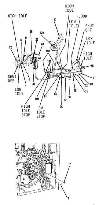
Governor Controls. (Sheet 19 of 21)
ADJUSTMENT
1.
Tighten nut (120) on operator’s control console
until position of handle (127) is not affected by
movement of treadles (86 and 84, Figure 3-176).
2.
Remove cotter pin (1) and pin (2, Figure 3-177)
from fuel injection pump governor.
3.
Separate rod end (7) and lever (12, Figure 3-176).
4.
Loosen two nuts (108) and bolts (109) under right
side of operator’s compartment. Turn bolts (109)
out far enough to keep lever (105) from making
contact.
5.
Position handle (127) in operator’s control console.
Push forward into low idle position.
6.
Adjust low idle bolt (109) under right side of
operator’s compartment until contact with
lever (105) is made.
7.
Tighten nuts (108).
8.
Remove nut (70), washer (71) and bolt (72).
9.
Separate lever (87) and two rod ends (91).
10.
Adjust two rod ends (91) until distance between
top of lever (87) and operator’s compartment
floor is 1.5 inch.
11.
Tighten two nuts (92).
12.
Aline two rod ends (91) and lever (87).
Go to Sheet 20
3-186
Figure 3-177.
Figure 3-176.