TM 5-3805-261-34
FUEL SYSTEM MAINTENANCE. (cont)
3-30.
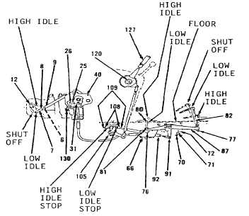
Governor Controls. (Sheet 21 of 21)
ADJUSTMENT (cont)
25.
Position lever (12) on fuel injection pump
governor and turn fully counterclockwise to high
idle position.
26.
Adjust link (9). Handle (127) must be in high
position. Adjust link (9) until pin (2) can be
installed through rod end (7) and lever (12).
27.
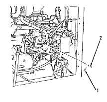
Install pin (2) and cotter pin (1, Figure 3-177).
28.
Tighten nuts (8 and 6, Figure 3-176).
29.
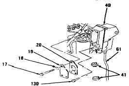
Install governor switch (130). Do not connect
wires to switch. Refer to TM 5-3805-261-20.
30.
Position lever (12) in shut-off position in
housing (40).
31.
Connect lamp tester to terminals on governor
switch (130) and adjust bolt (25) until lamp
lights dimly. Turn bolt (25) one additional turn.
Connect wire assemblies to governor switch
(130).
32.
Tighten nut (26).
INSTALLATION
1.
Install two new straps (41) around cable (61,
Figure 3-178) and governor switch wires.
2.
Install new gasket (20), cover (19), four
washers (18) and bolts (17).
NOTE
Return 130G Grader to original
equipment condition.
End of Task
3-188
Figure 3-178.
Figure 3-176.
Figure 3-177.