TM 5-3805-261-23-2
WHEEL SPINDLE, BEARINGS, AND SEALS REPLACEMENT - CONTINUED
0302 00
INSTALLATION - CONTINUED
8.
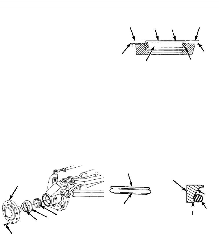
Measure at points (A through D), 90 degrees apart
B
A
20
D
with depth rule gauge. Check height from housing
surface to top of seal (20). Differences in heights
between points (A through D) must not exceed 0.04 in
(1.0 mm).
HOUSING
HOUSING
SURFACE
19
SURFACE
C
397-4186
9.
Adjust seal (20) and ring (19), if necessary, using a seal inserter.
NOTE
If any dirt particles remain on seal face, seal will leak.
10.
Clean seal (20) mating surface with a lint free cloth.
11.
Lubricate mating surface of seal (20) with gear lubricant.
12.
Inspect ring (19) for twists or bulges. Incorrect installation will result in seal (20) failure. If incorrect installation is obvi-
ous, repeat steps 6 through 11.
13.
Install 10 studs (15) on spindle (11). Tighten studs to 170 lb-ft (230 Nm).
14.
Install bearing (12) on spindle (11).
15.
Install ring (14) on seal (13). Ensure ring is not twisted and is seated properly on bottom of seal ramp and against retain-
ing lip.
13
20
11
RAMP
14
19
12
RETAINING LIP
13
14
397-4183
397-4181
15
0302 00-5

