TM 5-3805-261-23-2
OIL PUMP AND LINES REPLACEMENT - CONTINUED
0276 00
REMOVAL - CONTINUED
25
16.
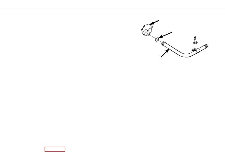
Remove elbow (25) from tube (27).
26
17.
Remove ring seal (26) from tube (27). Discard ring
seal.
27
397-2223
CLEANING AND INSPECTION
Clean and inspect all parts in accordance with WP 0020 00.
INSTALLATION
1.
Position tube (27) to oil pan plate.
2.
Install lock (18) and bolt (17). Bend lock tab up against bolt head.
3.
Use clean oil to lubricate outer diameter of new ring seal (26) and install ring seal on tube (27).
4.
Install elbow (25) on tube (27).
5.
Install elbow with scavenger tube (19) as an assembly, on oil pan plate.
6.
Install oil pan plate (WP 0275 00).
7.
Install key (24) on oil pump shaft (20).
8.
Install gear (21) on shaft (20).
9.
Install washer (22) and bolt (23). Tighten bolt to 32 lb-ft (43 Nm).
10.
Use driver and press to install new bearing (11), if removed. Install flush with outer face of gear (10).
11.
Install gear (10). Align mark on gear (10) with mark on gear (21).
CAUTION
Pump must be filled with clean oil to prevent initial startup damage.
12.
Use clean oil to lubricate oil pump (12).
13.
Position new gasket (13) and bell (16) on oil pump (12).
14.
Install lock (14) and two bolts (15). Bend lock tabs up against bolt heads.
NOTE
Proper timing of balancer shafts and oil pump gears is obtained when 3/8-16NC holes in balancer shafts are
in alignment with holes in oil pan plate and number one cylinder is at top center compression stroke.
15.
Locate top center of compression stroke of number one cylinder on engine (WP 0234 00).
0276 00-3

