TM 5-3805-261-20
BODY, CHASSIS AND HULL ACCESSORY ITEMS MAINTENANCE.
14-9.
Heater. (Sheet 6 of 7)
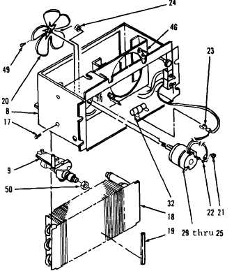
ASSEMBLY (cont)
14.
Install items 29 thru 25 as an assembly on
bracket (46, Figure 14-22).
15.
Install two nuts (24).
16.
Connect wire assembly (23) on resistor
(32).
17.
Connect wire assembly (22) at terminal.
18.
Install nut (21) on wire assembly (22).
19.
Position fan (20).
20.
Tighten screw (49).
21.
Install new seal (19) and coil (18) in heater
assembly (8).
22.
Install four screws (17).
23.
Position valve (9).
22.
Tighten nut (50).
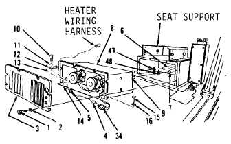
INSTALLATION
1.
Install heater assembly (8, Figure 14-21) in
front
seat
support
in
operator’s
compartment.
2.
Install washer (16) and bolt (15) in left side
of plate (14) of heater (8).
3.
Install washer (13), clip (12), lockwasher
(11) and bolt (10) in right side of plate (14)
of heater assembly (8).
4.
Connect hose (7) to valve (9).
Figure 14-22.
Figure 14-21.
Go to Sheet 7
14-38