TM 5-3805-261-20
BODY, CHASSIS AND HULL ACCESSORY ITEMS MAINTENANCE.
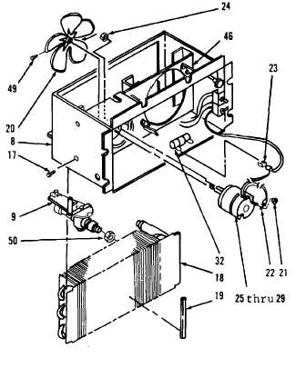
14-9.
Heater. (Sheet 3 of 7)
DISASSEMBLY
1.
Loosen nut (50) from heater assembly (8,
Figure 14-22).
2.
Remove valve (9) from inlet.
3.
Remove four screws (17).
4.
Remove coil (18) and seal (19). Discard
seal (19).
NOTE
The
following
steps
are
for
maintenance of the right side fan and
motor assembly, resistor and switch.
The maintenance procedure for the
left side fan and motor assembly,
resistor and switch is identical.
5.
Loosen screw (49).
6.
Remove fan (20).
7.
Remove nut (21) from wire assembly (22).
8.
Disconnect wire assembly (22) at terminal.
9.
Disconnect wire assembly (23) at terminal
from resistor (32).
10.
Remove two nuts (24).
11.
Remove items 25 thru 29 as an assembly
from bracket (46).
Figure 14-22.
Go to Sheet 4
14-35