TM 5-3805-261-20
BODY, CHASSIS AND HULL ACCESSORY ITEMS MAINTENANCE. (cont)
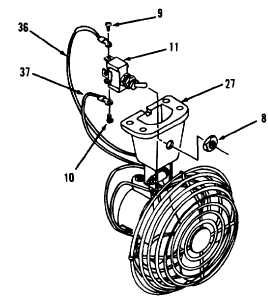
14-8.
Front and Rear Defroster Fans and Mounting. (Sheet 6 of 6)
ASSEMBLY (cont)
11.
Connect wire assembly (37) at terminal to
switch (11, Figure 14-18).
12.
Install screw (10) in switch (11).
13.
Connect wire assembly (36) at terminal.
14.
Install screw (9).
15.
Position switch (11) in base (27).
16.
Install nut (8).
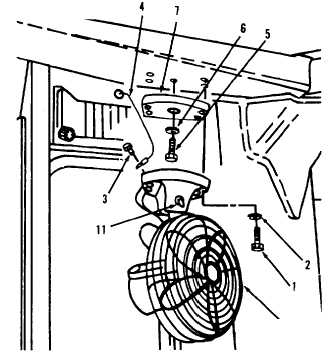
INSTALLATION
NOTE
Install plate, washer and bolt on rear defroster fan only.
Install plate on front defroster fan only.
1.
Install plate (7, Figure 14-17) on front
defroster fan only.
2.
Install plate (7), washer (6) and bolt (5) on
rear defroster fan only.
3.
Position items 41 thru 8 as an assembly.
4.
Connect wire assembly (4) at terminal to
switch (11).
5.
Install screw (3).
6.
Install four lockwashers (2) and bolts (1).
NOTE
Return
130G
Grader
to
original
equipment condition.
Figure 14-18.
Figure 14-17.
End of Task
41 thru 8
14-32