TM 5-3805-261-20
BODY, CHASSIS AND HULL ACCESSORY ITEMS MAINTENANCE. (cont)
14-6.
Rear Wiper. (Sheet 4 of 4)
INSTALLATION (cont)
2.
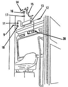
Position motor (21) and two brackets (20).
Adjust brackets (20) to a line with holes in
cover (13).
3.
Install screws (19 and 18).
4.
Install nut (17) on switch (16, Figure 14-12).
5.
Position switch (16) in cover (13).
6.
Install nut (11).
7.
Adjust nuts (17 and 11) to obtain proper
switch (16) shaft length.
8.
Connect three wire assemblies (15) and
wire assembly (14) to switch (16).
9.
Position cover (13) on two brackets (20).
10.
Install two screws (12).
11.
Install knob (10) and screw (9).
12.
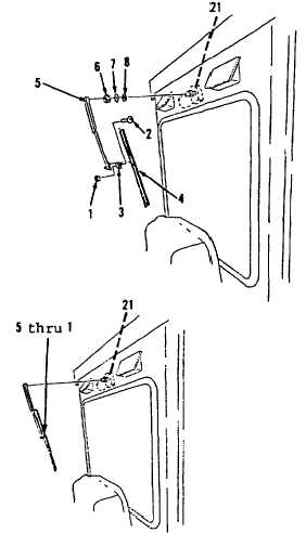
Install washers (8 and 7) and nut (6, Figure
14-11) in upper rear, exterior of cab.
13.
Position blade (4) and clip (3) on arm (5).
14.
Install screw (2) and nut (1).
15.
Install items 5 thru 1 as an assembly. Push
back on splined shaft of motor (21, Figure
14-10) at same angle as when removed.
NOTE
Return
130G
Grader
to
original
equipment condition.
Figure 14-12.
End of Task
Figure 14-11.
Figure 14-10.
14-22


