TM 5-3805-261-20
WIRING HARNESS MAINTENANCE.
7-133.
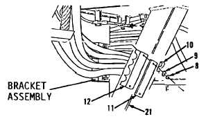
Disconnect Switch Cable. (Sheet 4 of 4)
INSTALLATION
7.
Position cable assembly (21) between two
clamps (12, Figure 7-219).
8.
Install two clamps (12) and plate (11).
9.
Install clip (10) on hose.
10.
Install two washers (9) and nuts (8) on
bracket assembly.
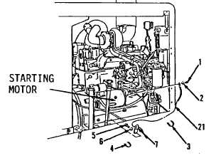
11.
Position cable assembly (21, Figure 7-
218) through rear frame, under engine and
across to right side of engine.
12.
Install two clips (7) on cable assembly (21)
on inner right side of rear frame.
13.
Install two washers (6) and bolts (5).
14.
Install new straps (4 and 3).
15.
Connect cable assembly (21) on starting
motor terminal on right side of engine.
16.
Install lockwasher (2) and nut (1). Tighten
nut (1) to 22 ft-lb torque.
NOTE
Return
130G
Grader
to
original
equipment condition.
Figure 7-219
Figure 7-218
End of Task
7-349