TM 5-3805-261-20
HORN AND BACK-UP ALARM MAINTENANCE. (cont)
7-105.
Back-up Alarm Switch. (Sheet 2 of 4)
REMOVAL
NOTE
All
wire,
cable
and
harness
assemblies must be tagged before
disconnecting to aid in installation.
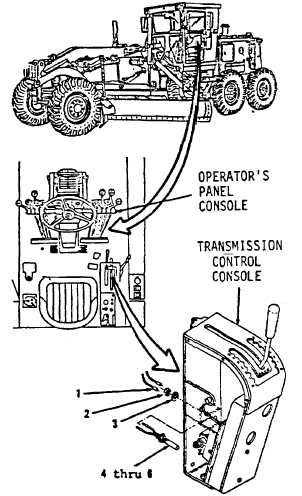
1.
Disconnect two wire assemblies (1, Figure
7-157)
on
inside
of
operator’s
panel
console.
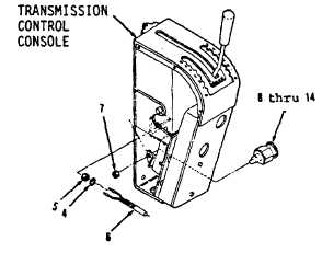
2.
Remove nut (5) and lockwasher (4) from
switch
assembly
(6).
Remove
switch
assembly (6). (Figure 7-155).
3.
Remove nut (2), lockwasher (3) from switch
assembly (6). (Figure 7-157).
4.
Remove nut (7) and items 8 thru 14 as an
assembly from plate inside transmission
control console.
Figure 7-157
Figure 7-158
Go to Sheet 3
7-256


