TM 5-3805-261-20
HORN AND BACK-UP ALARM MAINTENANCE.
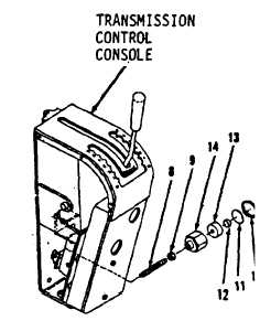
7-105.
Back-up Alarm Switch. (Sheet 3 of 4)
REMOVAL
5.
Remove stud (8) and nut (9) from holder
(14, Figure 7-159).
DISASSEMBLY
1.
Using snap ring pliers, remove ring (10.
Figure 7-159).
2.
Separate cover (11), magnet (12) and filter
(13) from holder (14).
CLEANING
Clean all parts. Refer to Chapter 2.
INSPECTION
Inspect all parts. Refer to Chapter 2.
ASSEMBLY
1.
Install filter (13), magnet (12) and cover (11)
in holder (14). Side of magnet (12) with part
number stamped must ace the direction of
cover (11. Figure 7-159).
2.
Install ring (10).
INSTALLATION
1.
Install nut (9) on stud (8, Figure 7-159) in
transmission control console.
2.
Install items 9 and 8 as an assembly in
holder (14). Apply thread sealant to
threads on stud (8).
3.
Seat nut (9) against holder (14) and tighten
nut (9) to 18 ft-lb torque.
Figure 7-159
Go to Sheet 4
7-257