TM 5-3805-261-20
HORN AND BACK-UP ALARM MAINTENANCE. (cont)
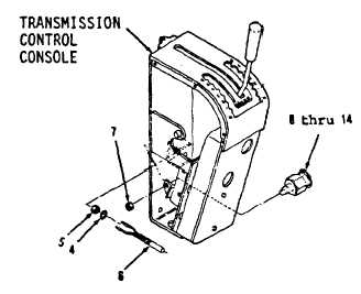
7-105.
Back-up Alarm Switch. (Sheet 4 of 4)
INSTALLATION (cont)
4.
Position items 14 thru 8 as an assembly in
plate (Figure 7-158).
5.
Install nut (7) loosely.
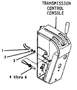
6.
Install lockwasher (3) and nut (2) on switch
assembly (6). (Figure 7-157).
7.
Position items 6 thru 4 as an assembly
(Figure
7-157)
through
weldment
in
operator’s compartment.
8.
Install lockwasher (4) and nut (5, Figure 7-
158).
9.
Connect two wire assemblies (1) to inside
of operator’s panel console.
ADJUSTMENT
1.
Position transmission forward-reverse lever
in reverse in transmission control console.
2.
Adjust nuts (9 and 7) until a clearance of
0.25 inch is made between switch assembly
(6) and items 14 thru 10 as an assembly.
3.
Tighten nuts (9 and 7).
NOTE
Return
130C
Grader
to
original
equipment condition.
Figure 7-158
Figure 7-157
End of Task
7-258