TM 5-3805-261-20
ELECTRICAL SYSTEM MAINTENANCE. (cont)
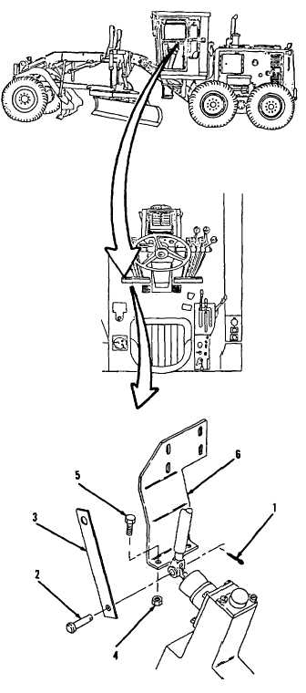
7-56.
Blade Float Limit Switch Mounting and Linkage. (Sheet 2 of 2)
REMOVAL
NOTE
The
following
is
a
maintenance
procedure for the left blade float limit
switch mounting and linkage. The
maintenance procedure for the right
blade float limit switch mounting and
linkage is identical.
1.
Remove cotter pin (1), pin (2) and plate (3,
Figure 7-75) from front, lower left side of
cab.
2.
Remove two nuts (4) and bolts (5).
3.
Remove bracket (6).
CLEANING
Clean all parts. Refer to Chapter 2.
INSPECTION
Inspect all parts. Refer to Chapter 2.
INSTALLATION
1.
Position bracket (6, Figure 7-75) on front,
lower left side of cab.
2.
Install two bolts (5) and nuts (4).
3.
Install plate (3), pin (2) and cotter pin (1).
NOTE
Return
130G
Grader
to
original
equipment condition.
Figure 7-75
End of Task
7-138