TM 5-3805-261-20
ELECTRICAL SYSTEM MAINTENANCE.
7-55.
Blade Float Limit Switch. (Sheet 2 of 3)
REMOVAL
NOTE
The
following
is
a
maintenance
procedure for the left blade float limit
switch. The maintenance procedure
for the right blade float limit switch is
identical.
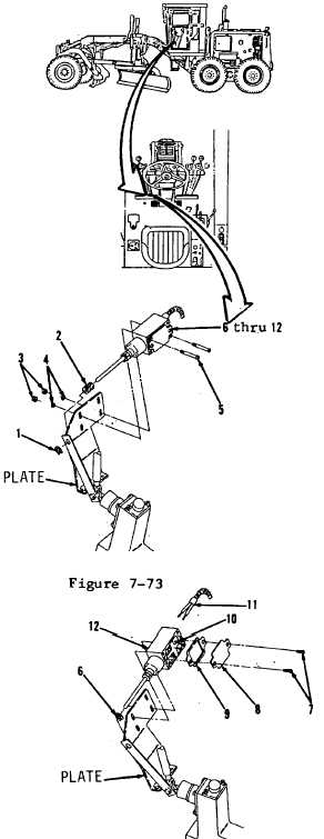
1.
Remove clip (1, Figure 7-73) from plate on
front lower left of cab interior.
2.
Remove spring (2).
3.
Remove two nuts (3), lockwashers (4) and
bolts (5).
4.
Remove items 6 thru 12 as an assembly.
5.
Remove clip (6, Figure 7-74).
6.
Remove two screws (7), plate (8) and
gasket (9). Discard gasket (9). Remove all
gasket material from mounting surfaces.
7.
Loosen two screws (10).
NOTE
All
wire,
cable
and
harness
assemblies must be tagged before
disconnecting to aid in installation.
8.
Disconnect two wire assemblies (11) from
switch (12).
Figure 7-74
Go to Sheet 3
7-135
Figure 7-73