TM 5-3805-261-20
SUPPLEMENTAL STEERING MAINTENANCE. (cont)
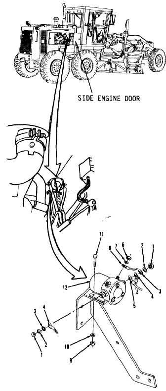
7-49.
Magnetic Switch. (Sheet 2 of 3)
REMOVAL
1.
Open right side engine door.
2.
Remove two nuts (1), lockwashers (2) and
washers (3, Figure 7-66) from front, left
side of engine compartment. Access is
from right side of engine compartment.
NOTE
All
wire,
cable
and
harness
assemblies must be tagged before
disconnecting to aid in installation.
3.
Disconnect cable assemblies (4 and 5) at
terminals.
4.
Remove two nuts (6) and lockwashers (7).
5.
Disconnect two wire assemblies (8) at
terminals.
6.
Remove four nuts (9), washers (10) and
bolts (11).
7.
Remove switch (12).
CLEANING
Clean all parts. Refer to Chapter 2.
INSPECTION
Inspect all parts. Refer to Chapter 2.
Figure 7-66
Go to Sheet 3
7-124