
TM 5-3805-293-23-5
0331
BATTERY CABLE INSTALLATION CONTINUED
000331
N OT E
Refer to battery cable installation parts list (Table 2) to correctly install and connect battery
cables.
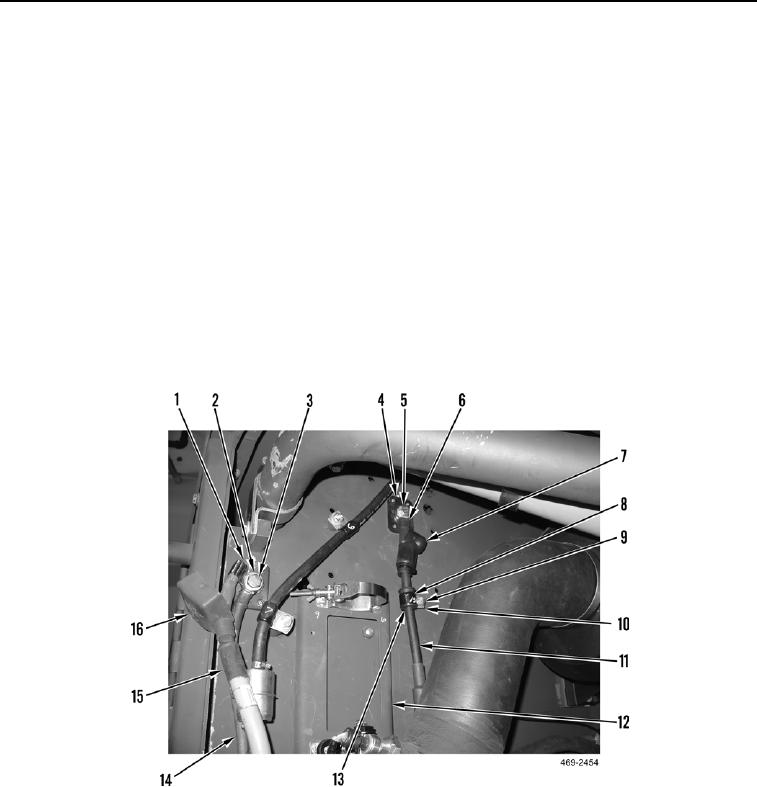
26. Route arctic kit negative cable assembly (Figure 18, Item 11) on hydraulic service pack (Figure 18, Item 12).
27. Install arctic kit negative cable assembly (Figure 18, Item 11), washer (Figure 18, Item 6), and bolt (Figure 18,
Item 5) on junction block (Figure 18, Item 4).
28. Position terminal cover (Figure 18, Item 7) over junction block (Figure 18, Item 4).
29. Route arctic kit positive cable assembly (Figure 18, Item 15) on hydraulic service pack (Figure 18, Item 12).
30. Install positive battery cable (Figure 18, Item 14), arctic kit positive cable assembly (Figure 18, Item 15),
washer (Figure 18, Item 2), and bolt (Figure 18, Item 3) on junction block (Figure 18, Item 1).
31. Position terminal cover (Figure 18, Item 16) over junction block (Figure 18, Item 1).
32. Install grommet (Figure 18, Item 13), clamp (Figure 18, Item 8), washer (Figure 18, Item 10), and bolt (Figure
18, Item 9) on hydraulic service pack (Figure 18, Item 12).
Figure 18. Battery Cable Bulkhead Connection.
0331