
TM 5-3805-293-23-5
0312
INSTALLATION
000312
N OT E
Install all lines as marked and tagged during removal.
1. Install new O-ring (Figure 7, Item 9) and connect tube (Figure 7, Item 8) to front valve (Figure 7, Item 1).
2. Route hose (Figure 7, Item 6) on machine. Install new O-ring (Figure 7, Item 7) and connect hose to tube
(Figure 7, Item 8).
3. Install new O-ring (Figure 7, Item 2) and connect tube (Figure 7, Item 3) to front valve (Figure 7, Item 1).
4. Route hose (Figure 7, Item 5) on machine. Install new O-ring (Figure 7, Item 4) and connect hose to tube
(Figure 7, Item 3).
N OT E
Install all lines as marked and tagged during removal.
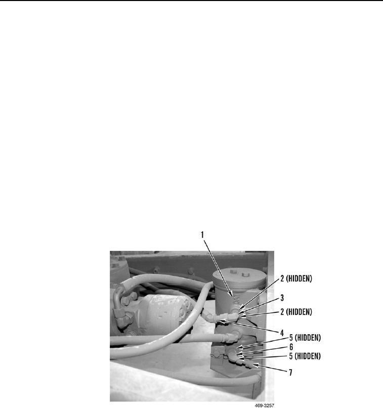
5. Install two new O-rings (Figure 8, Item 5) and elbow (Figure 8, Item 6) on swivel (Figure 8, Item 1).
6. Connect hose (Figure 8, Item 7) to elbow (Figure 8, Item 6).
7. Install two new O-rings (Figure 8, Item 2) and elbow (Figure 8, Item 3) on swivel (Figure 8, Item 1).
8. Route hose (Figure 8, Item 4) on machine. Connect hose to elbow (Figure 8, Item 3).
Figure 8. Left-Side Swivel Connections.
0312