
TM 5-3805-293-23-5
0281
REMOVAL CONTINUED
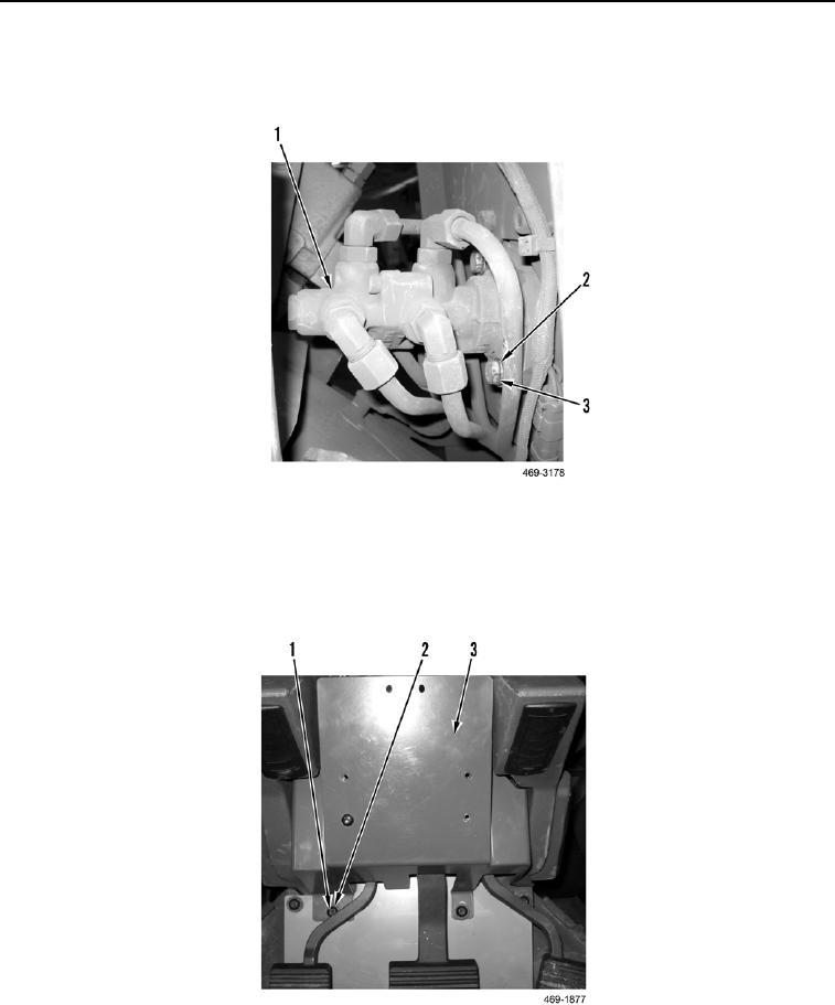
7. Remove two bolts (Figure 4, Item 3) and washers (Figure 4, Item 2) from service brake control valve (Figure 4,
Item 1).
Figure 4. Service Brake Control.
0281
8. Remove three bolts (Figure 5, Item 2) and washers (Figure 5, Item 3) from pedal assembly cover (Figure 5,
Item 1).
9. Remove pedal assembly cover (Figure 5, Item 1) from cab.
Figure 5. Pedal Assembly Cover.
0281