
TM 5-3805-293-23-4
0255
ASSEMBLY
000255
N OT E
Lubricate all O-rings and seals with a small amount of hydraulic oil before installation.
1. Install new wear ring (Figure 5, Item 5), new buffer seal (Figure 5, Item 4), new U-cup seal (Figure 5, Item 3),
new wiper seal (Figure 5, Item 2), new backup ring (Figure 5, Item 15), and new O-ring (Figure 5, Item 14) on
head (Figure 5, Item 1).
2. Install new wear ring (Figure 5, Item 12), new inner seal (Figure 5, Item 10) and new outer seal (Figure 5,
Item 11) on piston (Figure 5, Item 7).
3. Install head (Figure 5, Item 1) and piston (Figure 5, Item 7) on cylinder rod (Figure 5, Item 13).
4. Install washer (Figure 5, Item 8) and bolt (Figure 5, Item 9) on cylinder rod (Figure 5, Item 13). Torque to
443 lb-ft (600 Nm).
5. Install cylinder rod (Figure 5, Item 12) in cylinder housing (Figure 5, Item 6) and tighten head (Figure 5, Item 1)
to 443 lb-ft (600 Nm).
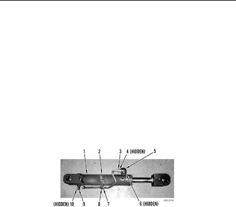
6. Install new O-ring (Figure 6, Item 10) and fitting (Figure 6, Item 9) on cylinder (Figure 6, Item 1).
7. Install new O-ring (Figure 6, Item 6) and fitting (Figure 6, Item 5) on cylinder (Figure 6, Item 1).
8. Install new O-ring (Figure 6, Item 4) and pipe (Figure 6, Item 3) on fitting (Figure 6, Item 5).
9. Install insert (Figure 6, Item 7) and clamp (Figure 6, Item 2) on cylinder (Figure 6, Item 1) and tighten screw
(Figure 6, Item 8).
Figure 6. Articulation Cylinder Pipes.
0255
END OF TASK

