
TM 5-3805-293-23-4
0232
INSTALLATION CONTINUED
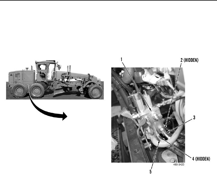
21. Install hose (Figure 22, Item 5) on machine.
22. Install new O-ring (Figure 22, Item 4) and connect hose (Figure 22, Item 5) to hydraulic fan and brake control
manifold (Figure 22, Item 1).
23. Install hose (Figure 22, Item 3) on machine.
24. Install new O-ring (Figure 22, Item 2) and connect hose (Figure 22, Item 3) to hydraulic fan and brake control
manifold (Figure 22, Item 1).
Figure 22. Front Hydraulic Fan and Brake Control Manifold.
0232

