
TM 5-3805-293-23-4
0232
INSTALLATION CONTINUED
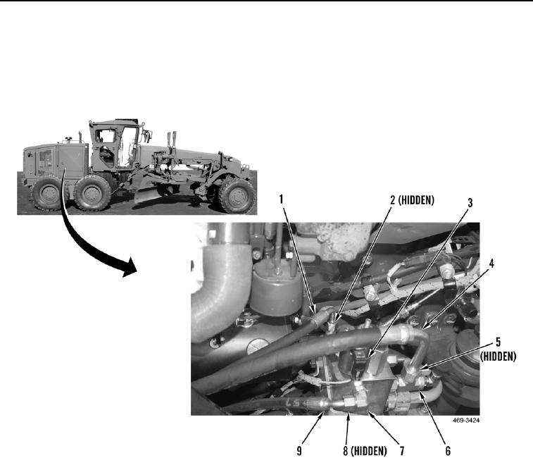
18. Install new O-ring (Figure 21, Item 8) and connect hose (Figure 21, Item 9) to elbow (Figure 21, Item 7).
19. Install new O-ring (Figure 21, Item 2) and connect hose (Figure 21, Item 1) to hydraulic fan and brake control
manifold (Figure 21, Item 3).
20. Install new O-ring (Figure 21, Item 5) and connect hose (Figure 21, Item 4) to tee (Figure 21, Item 6).
Figure 21. Right Hydraulic Fan and Brake Control Manifold.
0232

