
TM 5-3805-293-23-4
0218
FRONT VALVE BANK CONTINUED
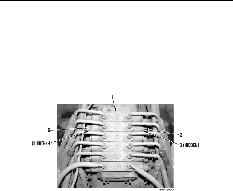
Sideshift Circuit
8. Slowly turn sideshift lock valve (Figure 7, Item 2) and sideshift relief valve (Figure 7, Item 5) three complete
turns. Allow pressure to release.
9. Remove sideshift lock valve (Figure 7, Item 2) and O-rings (Figure 7, Item 3) from manifold (Figure 7,
Item 1). Discard O-rings.
10. Remove sideshift relief valve (Figure 7, Item 5) and O-rings (Figure 7, Item 4) from manifold (Figure 7, Item 1).
Discard O-rings.
11. Install new O-rings (Figure 7, Item 4) on sideshift relief valve (Figure 7, Item 5). Install sideshift relief valve on
manifold (Figure 7, Item 1).
12. Install new O-rings (Figure 7, Item 3) on sideshift lock valve (Figure 7, Item 2). Install sideshift lock valve on
manifold (Figure 7, Item 1). Torque to 59 11 lb-ft (80 15 Nm).
Figure 7. Sideshift Circuit.
0218
Change 1

