
TM 5-3805-293-23-4
0216
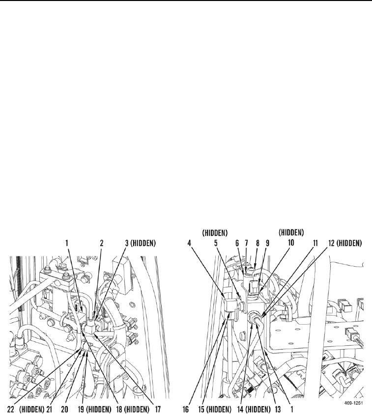
REMOVAL CONTINUED
3. Remove two locknuts (Figure 2, Item 8), washers (Figure 2, Item 7), sleeves (Figure 2, Item 6), cartridges
(Figure 2, Item 9), and six O-rings (Figure 2, Item 10) from steering backup valve (Figure 2, Item 1). Discard O-
rings.
4. Disconnect hydraulic tube (Figure 2, Item 2) and remove O-ring (Figure 2, Item 3) from elbow (Figure 2,
Item 17). Discard O-ring.
5. Remove elbow (Figure 2, Item 17) and O-ring (Figure 2, Item 18) from steering backup valve (Figure 2, Item 1).
Discard O-ring.
6. Disconnect hydraulic tube (Figure 2, Item 20) and remove O-ring (Figure 2, Item 19) from fitting (Figure 2,
Item 12). Discard O-ring.
7. Remove fitting (Figure 2, Item 22) and O-ring (Figure 2, Item 21) from steering backup valve (Figure 2, Item 1).
Discard O-ring.
8. Disconnect hydraulic tube (Figure 2, Item 11) and remove O-ring (Figure 2, Item 12) from fitting (Figure 2,
Item 13). Discard O-ring.
9. Remove fitting (Figure 2, Item 13) and O-ring (Figure 2, Item 14) from steering backup valve (Figure 2, Item 1).
Discard O-ring.
10. Disconnect hydraulic tube (Figure 2, Item 16) and remove O-ring (Figure 2, Item 15) from elbow (Figure 2,
Item 4). Discard O-ring.
11. Remove elbow (Figure 2, Item 4) and O-ring (Figure 2, Item 5) from steering backup valve (Figure 2, Item 1).
Discard O-ring.
Figure 2. Hydraulic Line Connections.
0216

